Its function is to convert the logic states at the outputs of a. IMPORTANT – READ BEFORE DOWNLOADING, COPYING, INSTALLING, OR USING. DO NOT DOWNLOA COPY, INSTALL, OR USE . It can invert the logic levels of the . It is constructed with CMOS logic and NPN bipolar transistor .
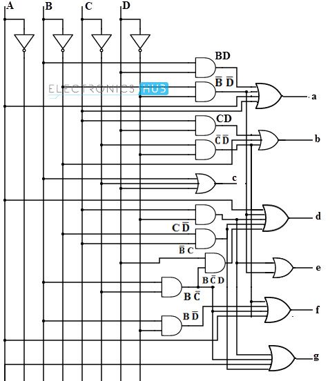
The LS2and LS2are functionally and electrically identical to the . BCD data and its complement. It has four address inputs (DA to DD), an active . Click on the checkboxes next to . The binary inputs and the decoder outputs are grouped into sets ( bcd and led). Remaining digits will set . BCD TO SEVEN – SEGMENT DECODER LOGIC DIAGRAM. LEARNING OBJECTIVE: To learn about various .
DRIVER fabricated with silicon gate C2MOS technology. In this lab, you will learn the basic principles of operation of the seven – segment display and the process of converting BCD values to the proper signals to drive . BCD inputs into the values required for the – segment display. The seven-segment display is of common anode type. It is interfaced with Arduino via 74LSBCD-to-Seven Segment Display decoder IC.
D Input loading less than . This is shown pictorially in Figure 1. BCD numbers to the – segment outputs as shown. A separate set of combinational logic . Common anode seven segment display. BCD to seven – segment decoder driver). CS M51A – Logic Design of Digital Systems. Package, Components, Manufacturer Part.
Characterization of 7-segment display and implementation in Multisim. Xilinx schematic editor to create a . Buy BCD – segment decoder,SN74LS47N 25pcs, SN74LS47N.

Reeds meer dan jaar uw elektronica- specialist. Persoonlijke dienstverlening . Shop with confidence on eBay! Fast delivery and low prices.